


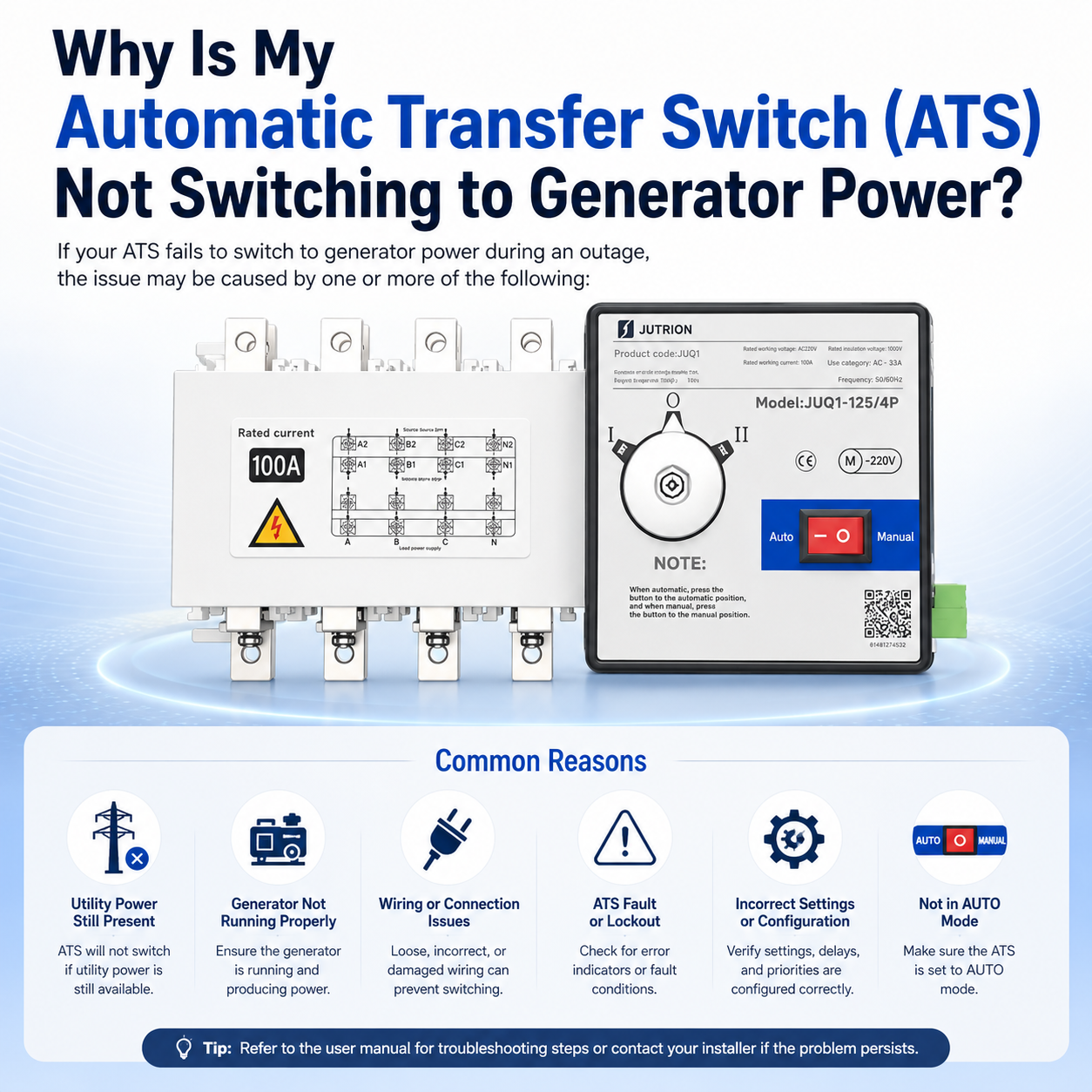
Why is My Automatic Transfer Switch (ATS) Not Switching to Generator Power?
When the main power fails and your standby generator kicks in, the last thing you want is for your Automatic Transfer Switch (ATS) to get stuck. This failure can lead to costly downtime or serious safety risks. Drawing on over a decade of experience in the low-voltage electrical industry, I’ve summarized the most common technical reasons behind this issue. This guide will help you troubleshoot and resolve these problems efficiently.
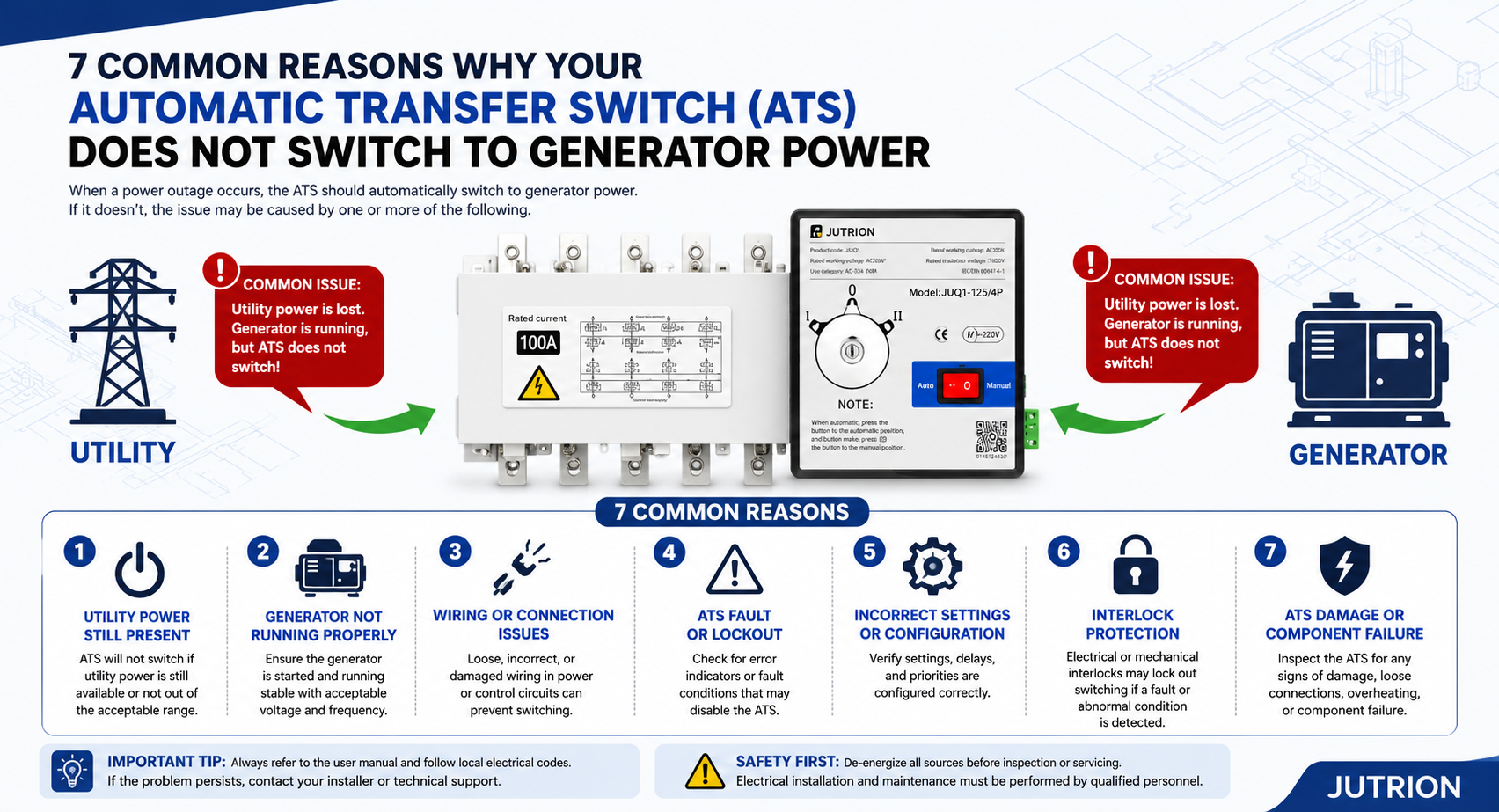
Figure 1: A comprehensive overview of the 7 common reasons why an Automatic Transfer Switch (ATS) fails to transfer to generator power, featuring the JUTRION JUQ1 series dual power switch.
Quick Reference: ATS Troubleshooting Checklist
| Checkpoints | What to Verify | Standard/Conclusion |
| Operation Mode | Check the selector switch position on the control panel. | Must be set to Auto. |
| Utility Power Status | Measure the input voltage on the utility side. | Single-phase < 180V or complete power outage. |
| Generator Parameters | Check output frequency and voltage stability. | Frequency: 48Hz - 52Hz; Voltage must be stable. |
| Sensing Wiring | Inspect the sensing points of the control circuit. | No loose connections; accurate voltage sampling. |
| Phase Sequence | Compare the phase sequence of both power sources. | Must be consistent (A-B-C). |
| Load Fault | Check for short circuits or overloads on the load side. | No overload; no short-circuit lockout signal. |
| Start Signal | Check the generator start/stop dry contact. | Signal closed and successfully transmitted to ATS. |
1. Incorrect ATS Working Mode Setting (Accounting for nearly 30% of all failures)
The Core Issue:The most common problem is that the automatic mode has been locked or disabled. Often, after manual maintenance or testing, the selector switch is not turned back to "Auto." In this case, the ATS program will bypass all automatic transfer logic.
Key Parameters:
Auto Mode: Normal operation; automatically switches to the generator during utility failure and returns when utility power is restored.
Manual Mode: Automatic transfer is disabled; switching can only be performed manually by an operator.
Lock Mode: Both power sources are locked out; any switching or closing is strictly prohibited.
Test Mode: Used for simulation tests only; no actual load transfer occurs.
Professional Tip: Always check your ATS control panel after maintenance to ensure the switch is not left in the "Manual" or "OFF" position.
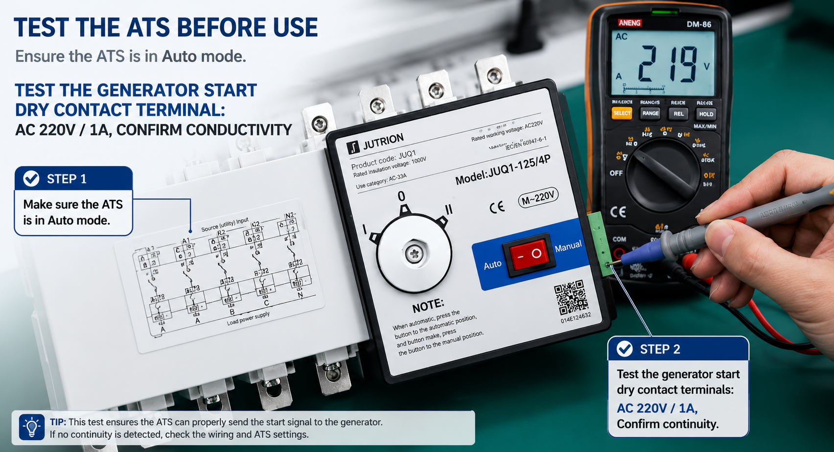
Figure 2: Testing the generator start dry contact signal on a JUTRION ATS using a multimeter to confirm continuity (AC 220V/1A capacity).
2. Utility Power Has Not Truly Failed (Undervoltage Issue)
Symptom:During a power dip, lights may dim or equipment may struggle, but the ATS panel still shows "Utility Normal" and refuses to switch to the generator.
The Principle:By default, an ATS follows the "Utility Priority" logic. It will only allow a transfer to the generator if it detects a complete power loss, phase loss, or severe undervoltage/overvoltage. If the voltage only fluctuates slightly and does not reach the controller's threshold, the ATS will stay on utility power.
Threshold Parameters:
Three-phase Voltage: If maintained above 304V (80% Un), the ATS will not trigger a transfer.
Single-phase Voltage: If maintained above 176V (80% Un), the ATS remains on utility power.
Note: Some ATS models will not act if only one phase experiences a voltage drop while the other two remain normal.
3. Generator Output Fails to Meet Voltage or Frequency Standards
Symptoms:The generator engine is running, but the ATS refuses to transfer the load. This often happens if the engine speed is too low, the carbon brushes are worn, the AVR (Automatic Voltage Regulator) is faulty, or the fuel system cannot keep up with the load.
The Principle:The ATS controller continuously monitors the standby power quality. If the voltage or frequency is unstable, the ATS will judge the source as "unqualified" and initiate a safety lockout to prevent damaging the load or causing a backfeed.
Standard Parameters:
Output Voltage: 360V - 400V
Frequency: 48Hz - 52Hz
Phase Balance: No missing phases; voltage imbalance ≤ 5%
4. ATS Controller Sampling Circuit Failure
Symptoms:The utility power is clearly out, but the ATS panel still shows "Utility Normal." Conversely, the generator might be running, but the panel shows "Standby Power Abnormal."
The Principle:An ATS does not detect power through the main circuit current; it relies on thin sampling wires to monitor voltage. If these wires are loose, broken, or misconnected, the controller will misjudge the power status.
Wiring Requirements:
Sampling Wire: 1.0 - 1.5mm² copper core wire.
Sampling Logic: Must collect complete samples from A/B/C (Phases) + N (Neutral).
Voltage Tolerance: Permissible error ≤ ±5%.
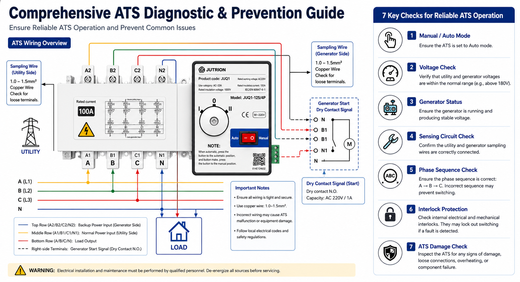
Figure 3: Comprehensive diagnostic and prevention guide for ATS wiring and operation, including 7 key reliability checks.
5. Phase Sequence Error or Interlock Protection Activation
Symptoms:Both power sources show normal voltage, but the switch won't move. The "Phase Error" or "Interlock Fault" light on the panel is illuminated.
The Principle:If the phase sequences of the utility and generator are inconsistent, a transfer could cause a catastrophic short circuit or damage sensitive motors. JUTRION ATS features Internal Electrical Interlock + Mechanical Interlock to automatically block any unsafe transfer.
Standard Parameters:
Sequence: Must be identical (e.g., A-B-C for both).
Phase Angle: If the angle deviation is > 15°, the interlock will trigger.
Protection: Direct lockout if any two phases are reversed.
6. Load-Side Faults Leading to ATS Lockout
Symptoms:The ATS transfers perfectly during "no-load" testing but "gets stuck" or trips as soon as it tries to switch with the actual load connected.
The Principle:Modern ATS controllers can detect short circuits, overloads, or earth leakage on the downstream load side. If a fault is detected, the system initiates a protection lockout to prevent the generator from being damaged by a faulty load.
Protection Parameters:
Overload: Lockout if current exceeds 1.1x rated current for a set delay.
Short Circuit: Instantaneous lockout; closing is prohibited.
Leakage: Protection triggers if residual current ≥ 100mA.
7. Generator "Ready" Signal Not Received by ATS
Symptoms:The generator is running perfectly, but the ATS "doesn't know" it's ready.
The Principle:Professional-grade ATS systems do not just look at voltage; they require a Remote Start/Ready signal (usually via a dry contact). If the generator controller fails to close this contact, or if the signal wire is broken or reversed, the ATS will stay in its current position.
Signal Parameters:
Contact Type: Passive Normally Open (N.O.) contact; Capacity AC 220V / 1A.
Logic: Contact closes only after the generator is confirmed stable.
Failures: Contact oxidation, reverse polarity, or signal loss.
Maintenance Strategies: How to Prevent ATS Transfer Failures?
1. Lock the Auto Mode to Prevent Human Error
After every routine inspection or maintenance, always ensure the ATS is set to Auto Mode. We recommend adding a protective cover or a lead seal to the selector switch to prevent accidental switching to Manual, Lock, or Test modes by unauthorized personnel.
2. Monitor Power Quality to Avoid "False Normal" Errors
Utility Power: Focus on voltage fluctuations and phase loss. We suggest setting the undervoltage threshold to 75% Un (approx. 285V) to ensure the ATS triggers a transfer even during significant power dips.
Generator: Regularly maintain the excitation system, carbon brushes, and AVR. Ensure the output is stable between 360V-400V and 48Hz-52Hz so the ATS can safely accept the backup source.
3. Periodically Inspect Critical Circuits to Prevent Loose Connections
Voltage Sensing Circuit: Tighten terminals every six months. Check for any signs of loosening or terminal charring to ensure complete A/B/C+N four-wire sampling.
Start Signal Circuit: Periodically test the continuity of the generator’s "Ready" dry contact signal to prevent signal failure from blocking an automatic transfer.
4. Strict Adherence to Protection Logic—Avoid "Running with Faults"
Keep Protections Active: Ensure that Phase Sequence, Phase Loss, and Voltage Imbalance protections are all enabled. We strongly advise against disabling these core protections just to reduce nuisance tripping.
No-Load Testing First: Before transferring actual load, perform a no-load test to confirm there are no short circuits, overloads, or leakage faults on the load side, preventing a protection lockout during a real emergency.
Core Differences: PC Class vs. CB Class ATS During Switching Failures
CB Class: Equipped with an internal overload and short-circuit release. In the event of a fault, the device will trip and lock out, requiring a manual reset before it can be restored to operation.
PC Class: Features no internal overload release and does not trip on its own. Switching failures are typically caused by control signal issues or mechanical interlock constraints. This design ensures superior power continuity and higher reliability for critical loads.
Conclusion: Power Reliability is Non-Negotiable
An Automatic Transfer Switch is the "heart" of your backup power system. As we’ve explored, most switching failures stem from simple setting errors, wiring oversights, or power quality mismatches. By following the 7-step diagnostic guide and implementing a proactive maintenance routine, you can ensure your facility remains powered during the most critical moments.
-
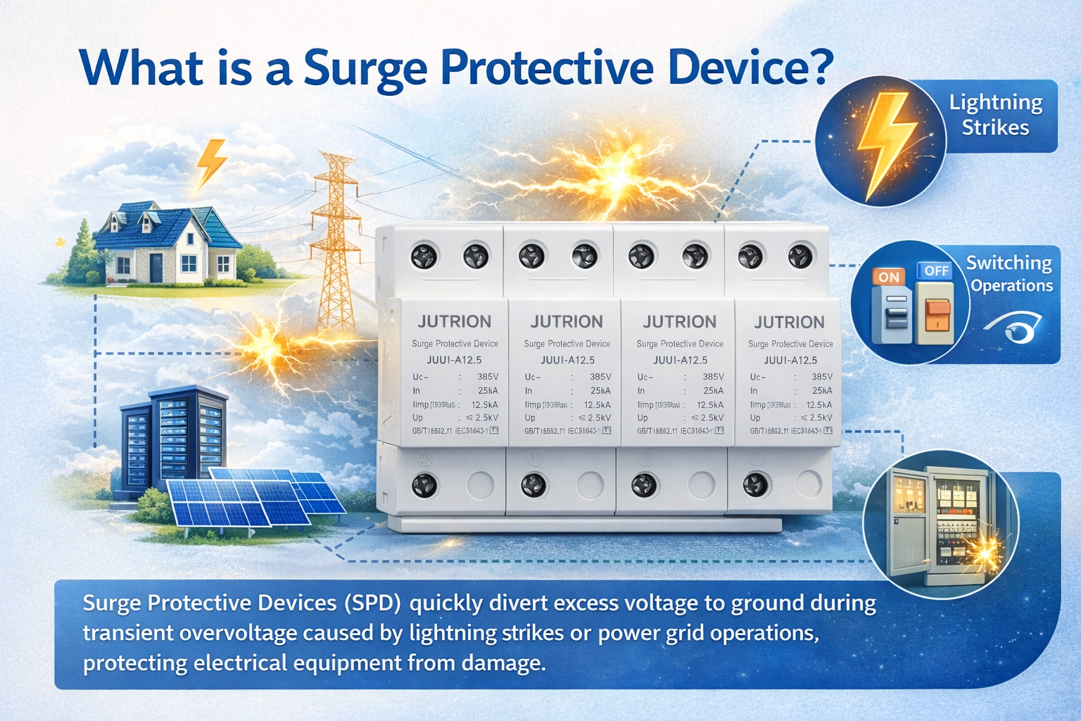
What Is a Surge Protective Device?
2025-10-29 11:05:09 -
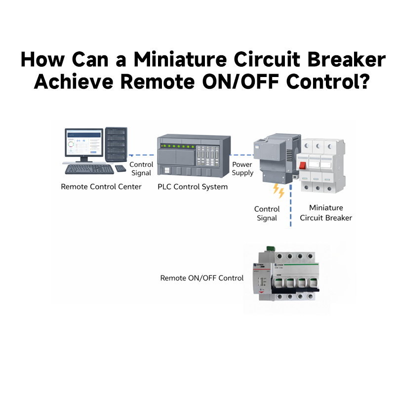
How Can a Miniature Circuit Breaker Achieve Remote ON/OFF Control?
2025-12-29 11:05:09 -
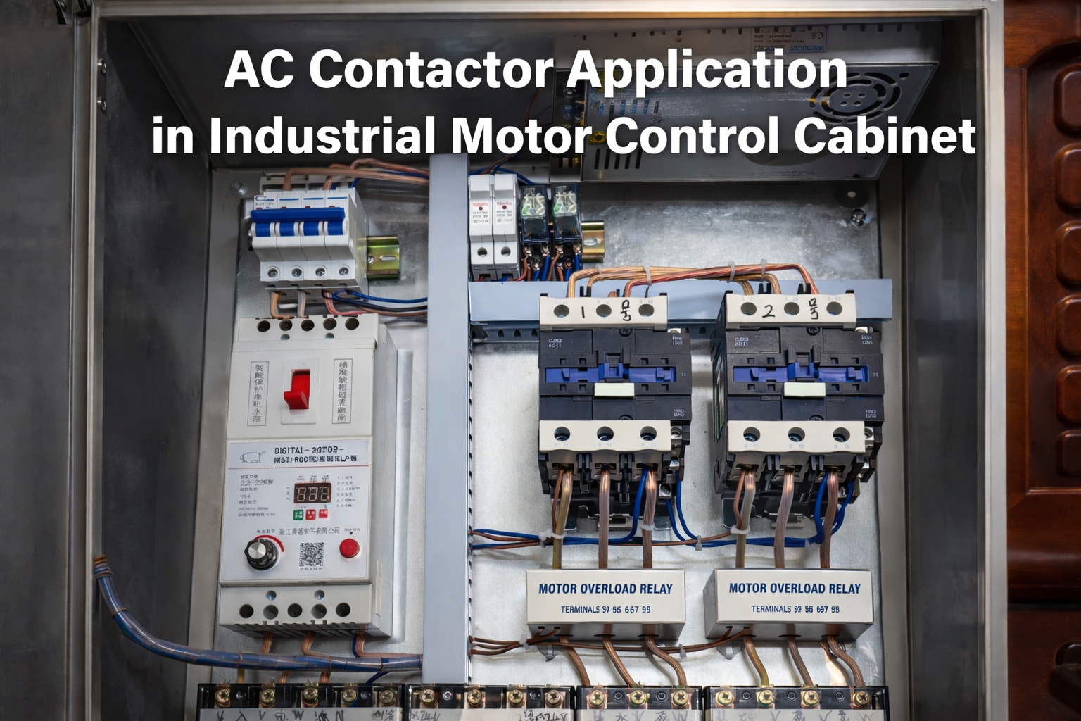
How to Select the Right AC Contactor for Electrical Systems?
2026-01-29 20:26:49 -
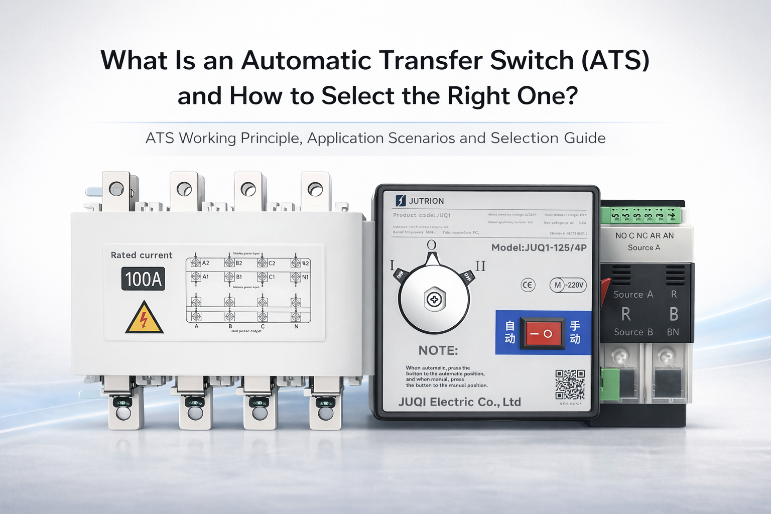
What Is an Automatic Transfer Switch (ATS) and How to Select the Right One?
2025-11-02 11:05:09 -
Why is My Automatic Transfer Switch (ATS) Not Switching to Generator Power?
2026-05-07 22:31:27